Jacking Pipe Procedure:
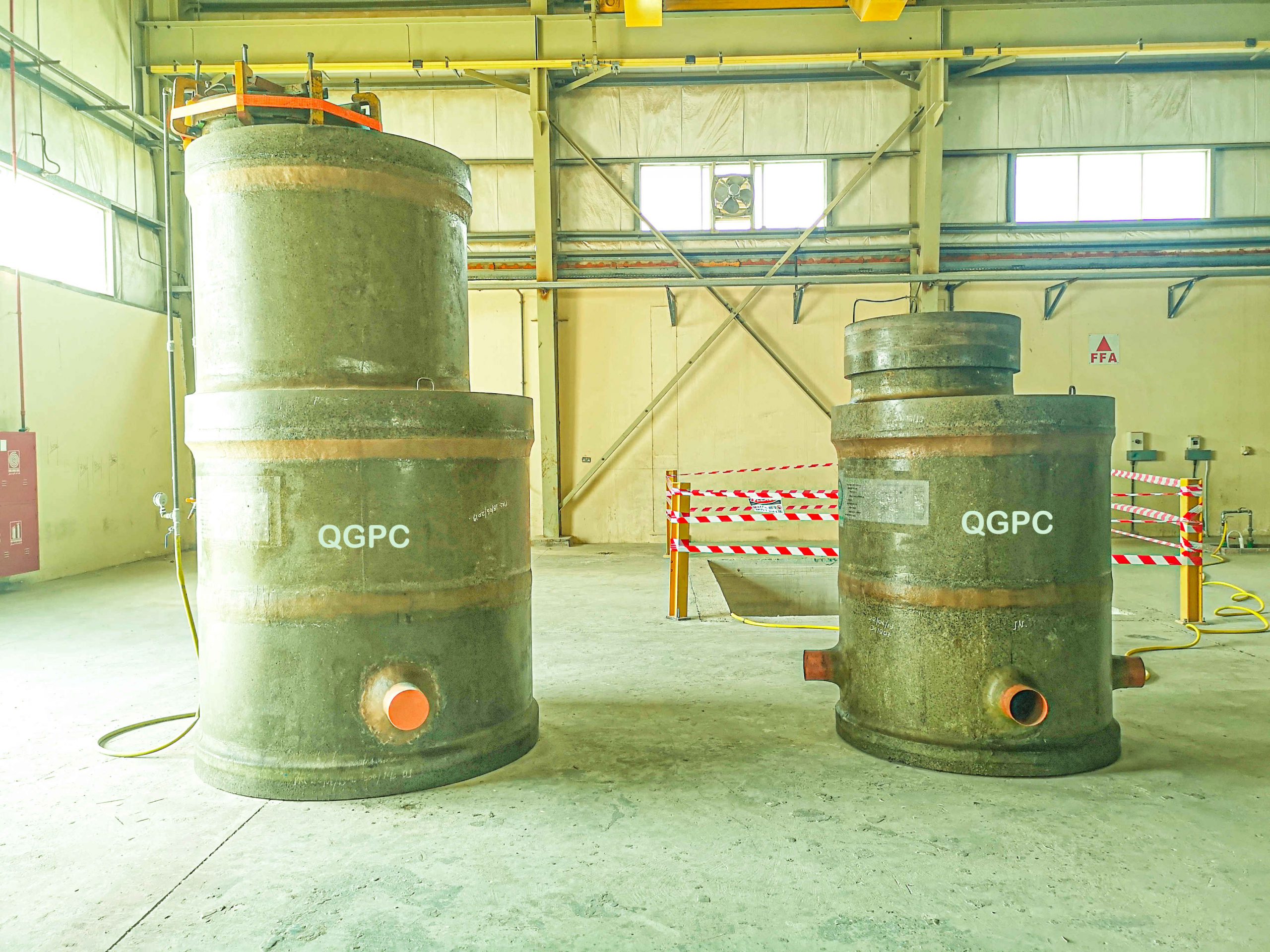
On delivery from the pipe manufacturer, each pipe will be checked at the proposed storage area for:
- Soundness of structure
- Any damage to inner or outer lining
- Any damage to gasket/seals
- Compression ring is not damage
- The overall shape of the pipe is correct and there are no undulations in the shape.
- The pipe unloading either by padded hooks or soft slings, so the pipes are not damaged.
- The truck for carrying the pipes is designed to transport pipes properly.
- The equipment (e.g., Crane sling – Clamps or stops are correct and will not damage the pipes or pipes linings).
- After transporting the pipes, gasket and inner lining will be rechecked, and then pipes will be documented.
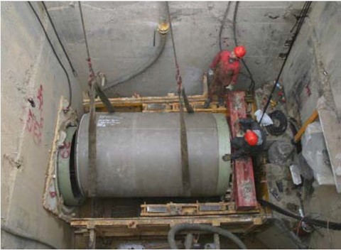
- As pipes are lowered into the jacking frame another visual inspection will take place in the shaft.
- Then pipes are launched into the tunnel.
- A daily record sheet is kept, describing each pipe, its condition, numbers and date of launching.
Tunneling Sequence:

- Before start of works, trial pits shall be carried out, to locate the existing utility pipeline location and depth.
- In micro tunnel there’s maximum length can be done with each machine according to its OD, in order to make one drive with long distance (proposed line), therefore the micro tunneling is divided the drive into portions, where each portion can be done using different machine OD according to the portion’s length.
- Micro tunneling with intermediate jack station shall be for long tunnels (more than 160 m).
- Structural excavation for the launching and reception shaft shall be carried out using excavator with hammer and bucket and the pit shall be excavated with the size (mentioned in shop drawings) with required depth and the excavated material shall be disposed-off to discharge area agreed with engineer’s representative.
- Prior to commencing (more than 1.5m depth), the side shall be stepped or sloped for protection against edge collapse or edge face protection to be provided according to site condition.
- Ensure suitable dewater system shall be provided if the excavation extends to below ground water table and site the condition necessitates.
- Ensure during excavation work continuous monitoring by surveyor to avoid over excavation, any such over excavation is to be backfilled with blinding concrete as same as the blinding.
- Construction dewatering from open excavation or trenches will be carried out using one of the following methods as per site condition:
- Gravity dewatering from sump points along the trench length and dewatered using a 6” diesel pump.
- Dewatering from well points installed adjacent to the trench and dewatered using a vacuum pump unit which is linked to a header line. Dewatering Lagoons: If required Dewatering lagoons licensed by MOE will be installed above ground by building a 1500mm high earth bund using excavated material compacted in layers.Discharge water tankers can also be used to discharge water.
The blinding shall be carried out with the required size and level. After the excavation and construction of the launching shaft, the following sequence of procedures will take place:
- Setting up of a datum on the tunnel centerline across the shaft.
- Jacking frame is lowered into the shaft using crane.
- Jacking frame is set to the correct level and grade of the intended drive.
- Thrust wall will be cast in site between the jacking frame and shaft wall.
- Install the launch seal at the correct position.
- Install the laser mounting bracket and set the laser to the drive coordinates at which point the frame should be re-checked.
- Set up properly the control container and carry out all necessary electrical connections whilst abiding by the prevailing safety regulations pertinent to electrical installations.
- Install the slurry pump in the shaft and properly connect it to the socket provided in the control container.
- Install the feed and slurry water lines, ensuring that all said lines are properly secured.
- Connect all electrical cables and hydraulics between the control container and cutting shield and carry out a complete function test run prior lowering the shield into the shaft.
Lowering the TBM machine using crane and placed into the jacking frame.

- Connect all electrical cables, hydraulics, feed and slurry lines to the AVN.
- Input all data into the computer relevant to the drive such as, project title and drive, grade and correction data.
- Once the target information shows that the machine is on the correct path/axis (line and level) of the drive then the tunneling will be commenced.
- Assembling Interjack stations inside pipes and install them in tunnel at required distances depends on soil conditions.
- All spoil material will be pumped out of the lines to separation plant.
- One shift (10-12hr) will be conducted daily 6 days/week.
- Daily record sheets will be submitted to the Engineer’s representative for monitoring and recording daily progress and tunnel alignment.
- Each pipe gasket will be visually inspected at the top of the shaft and after lowering into the shaft and recorded. Records will be passed to the engineer weekly; however, they can be viewed on a daily shift bas
- Bentonite will be pumped in the annular space around the pipes to reduce the jacking force (if needed).
- Continue pushing until the machine break through.
- w. After breakthrough we take out the machine, feed and slurry pipes, and all service connections.
- Environmental protection: The slurry water comes out during tunnelling activity is transferring to a separation plant. The plant separates muck and water and the clear water send to tanks for feeding the crushing chamber. The remaining muddy water and muck dispose to designated areas. (As per approved relevant permit)
- Most of the equipment used in the process is with enclosure design. So, the generation of sound is comparatively less.
- JEC provides adequate spot lights to illuminate the shafts especially in night shifts and in poor vicinity. In usual cases the excavated shaft ventilation (forced and extract) is provided in tunnel when required.
- Angular deflection and alignment of the pipes shall be monitored by the Contractor during the drive operations. Monitoring line & level as per QCS2014, section 8, part 9. The angular deflection will not exceed the design assumption for the liner.
- Intermediate jacking pits. “Intermediate jacking pit” it is actually a regular jacking pit, its role is only to divide the one drive into two portions, and use of the same equipment as any regular jacking pit (jacking frame, control, separation, TBM machine, and it’s special equipment used in the middle of the tunnel, it is installed inside a special pipe called (intermediate jacking pipe), this pipe is installed inside the drive and the station inside it, where it’s role is to distribute the pushing force. Intermediate jacking pit will be used only if required by approved design consultant engaged by contractor.
- The invert level of the finished pipeline on the drive shaft shall be within ±10 mm of required level. the deviation limits of the invert and line of the pipeline as per the below table from QCS2014, section 8, part 9, clause 9.2.3.